Overview of Ultrasonic Flaw Detection
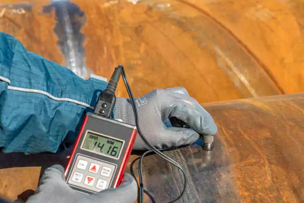
Ultrasonic flaw detection is a non-destructive testing (NDT) technique that uses high-frequency sound waves to detect imperfections in materials. By transmitting these sound waves into a material under investigation and analyzing the sound waves that are reflected or transmitted back, we can gain insights into the internal structure of the material. The ultrasonic flaw detector is the key instrument used in this technique. This method is especially effective for inspecting dense materials like metals, where traditional visual inspections may not be feasible.
Basic Theory of Ultrasonic Flaw Detection
Fundamentals of Sound Waves
Mechanical Vibrations
Sound waves are mechanical vibrations that travel through a medium. These vibrations are generated by a transducer in the ultrasonic flaw detector, converting electrical energy into mechanical energy. When these vibrations propagate through a medium, they can reflect or transmit at material boundaries.
Propagation Through Different Media
Different materials affect the propagation of sound waves differently. Factors such as density, elasticity, and internal structure can influence the speed and attenuation of sound waves. Understanding these properties is crucial to accurately analyzing the signals received from the ultrasonic testing.
Frequency of Sound Waves
Definition and Measurement
Frequency, measured in Hertz (Hz), is the number of vibrations per second. In ultrasonic testing, frequencies typically range from 1 MHz to 15 MHz, which are beyond the audible range for humans.
Audible vs. Ultrasonic Frequencies
Audible frequencies range from 20 Hz to 20 kHz, whereas ultrasonic frequencies are above 20 kHz. Ultrasonic frequencies allow for finer resolution in detecting small flaws within materials, making them ideal for industrial applications.
Velocity of Sound Waves
Speed in Various Media
The speed of sound waves varies with the medium. In air, sound travels at approximately 343 meters per second (m/s), while in steel, it travels around 5900 m/s. This variation is due to differences in density and elasticity.
Influence of Density and Elastic Properties
The denser and more elastic the material, the faster the sound wave travels. For instance, metals have higher sound velocities than polymers due to their higher density and elasticity.
Wavelength of Sound Waves
Definition and Calculation
Wavelength is the distance between successive points of a wave in phase. It is calculated using the formula λ = v/f, where λ is wavelength, v is velocity, and f is frequency.
Relationship Between Frequency and Velocity
There is an inverse relationship between frequency and wavelength for a given velocity. Higher frequencies result in shorter wavelengths, which can detect smaller flaws.
Modes of Propagation
Longitudinal Waves
In longitudinal waves, particle movement is parallel to wave propagation. They are primarily used in ultrasonic flaw detection due to their efficient energy transmission through solids and liquids.
Shear Waves
Shear waves have particle movement perpendicular to wave propagation. They travel slower than longitudinal waves and are used for detecting flaws that lie perpendicular to the wave path.
Surface Waves
Surface waves travel along the surface of a material and are used to detect surface flaws. They decay rapidly with depth, making them suitable for near-surface inspections.
Plate Waves
Plate waves propagate in thin materials with a laminar structure. They are used to detect flaws in thin sections such as sheets and plates.
Variables Limiting Transmission
Beam Spreading
Beam spreading occurs when the diameter of the sound beam increases with distance, reducing signal intensity. This can affect the clarity and accuracy of flaw detection.
Attenuation
Attenuation is the gradual loss of signal strength due to the absorption and scattering of sound energy in the material. It is influenced by material properties and wave frequency.
Scattering
Scattering happens when sound waves encounter particles or inclusions within the material, causing signal distortion. Understanding scattering effects is vital for accurate flaw define using ultrasonic techniques.
Reflection at a Boundary
Reflection Coefficient
The reflection coefficient measures the proportion of sound energy reflected at a boundary. It is determined by the acoustic impedance of the materials on either side of the boundary.
Acoustic Impedance
Acoustic impedance is the product of material density and sound wave velocity. Differences in acoustic impedance at boundaries lead to varying degrees of reflection and transmission.
Angle of Reflection and Refraction
Snell’s Law of Refraction
Snell’s Law defines the relationship between the angles of incidence and refraction when sound waves pass through different media. The law is essential for interpreting the paths of sound waves in complex geometries.
Practical Implications for Testing
Understanding the principles of reflection and refraction helps optimize probe orientations and testing angles in practical applications, improving the accuracy of ultrasonic flaw detector readings.
Ultrasonic Transducers
Definition and Function
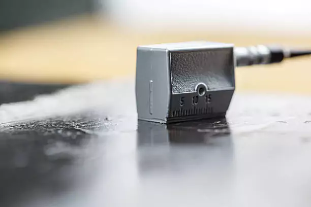
Ultrasonic transducers are the heart of the ultrasonic flaw detector. They serve the critical function of converting electrical energy into mechanical energy (sound waves) and vice versa. The accuracy and effectiveness of flaw detection are highly reliant on the performance of these transducers.
Energy Conversion
Transducers operate by converting electrical pulses into mechanical vibrations and back again, using electromechanical components. When a voltage is applied to the transducer, it vibrates and generates sound waves that travel into the material under inspection. Once these waves encounter a flaw, such as a crack or inclusion, they reflect back to the transducer, which then converts these mechanical reflections back into electrical signals for analysis. This bidirectional energy conversion is fundamental to the entire ultrasonic testing process.
Piezoelectric Elements
The core component within the transducer responsible for this energy conversion is the piezoelectric element. Piezoelectric materials have the unique property of changing shape when an electrical field is applied, and conversely, they generate an electrical charge when mechanically stressed. Common piezoelectric materials used in ultrasonic transducers include quartz, PZT (lead zirconate titanate), and PVDF (polyvinylidene fluoride). The selection of piezoelectric material impacts the sensitivity, frequency response, and reliability of the transducer, directly influencing the precision of flaw detection.
Types of Ultrasonic Transducers
Different types of ultrasonic transducers are designed to suit varying inspection requirements. Understanding these types can help streamline the process of flaw detection and ensure a comprehensive evaluation of materials.
Contact Transducers
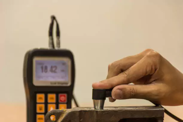
Contact transducers are designed to be in direct contact with the material being inspected. This necessitates the use of a couplant, such as glycerin or water, to facilitate efficient transmission of ultrasonic waves between the transducer and the material. The primary benefit of contact transducers is their ability to generate high-amplitude signals, making them suitable for detecting small flaws.
Applications
Contact transducers are widely utilized in scenarios where access to the inspection surface is feasible. They are commonly used for detecting internal cracks, voids, and inclusions in both manufactured components and structural elements. Industries such as aerospace, automotive, and construction frequently employ contact transducers for routine inspections and quality control.
Advantages and Limitations
One of the significant advantages of contact transducers is their ability to generate clear and high-definition signals, which enhances the accuracy of flaw detection. They are also versatile, suitable for a variety of materials and thicknesses. However, their direct contact requirement can be a limitation in certain scenarios. Surface roughness, cleanliness, and the necessity of a couplant can add complexity to the testing procedure. Additionally, if the material surface is inaccessible or hazardous, contact transducers may not be the optimal choice.
The ultrasonic flaw detector and flaw define processes heavily rely on selecting the appropriate transducer type to achieve the most accurate and reliable results. Understanding the nuances of contact transducers and their specific applications ensures that the best possible tools are employed for maintaining material integrity and safety in various industrial sectors.
Ultrasonic Flaw Detectors
Definition
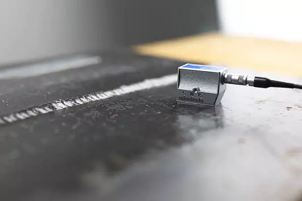
An ultrasonic flaw detector is a sophisticated instrument designed to identify flaws within a material by means of ultrasonic waves. This device emits pulses of high-frequency sound waves and captures any reflected signals to detect inconsistencies in the material.
Basic Components
The basic components of an ultrasonic flaw detector include a pulser/receiver, a transducer, a signal processor, and a display unit. The pulser initiates the sound waves, the transducer converts them into mechanical energy, the signal processor interprets the reflected waves, and the display unit visualizes the data for analysis.
Modern Ultrasonic Flaw Detectors
Digital Signal Processing
Modern ultrasonic flaw detectors utilize digital signal processing (DSP) to enhance the accuracy and speed of flaw detection. DSP capabilities enable advanced filtering, signal enhancement, and precise defect characterization.
Microprocessor-Based Instruments
Microprocessor-based instruments offer superior performance due to their ability to handle complex algorithms and provide real-time data analysis. These instruments improve the efficiency of flaw detection by automating many aspects of the testing process.
Key Features
Pulser/Receiver Section
The pulser/receiver section is crucial in generating and receiving ultrasonic waves. It produces high voltage pulses that drive the transducer and amplifies the returning echoes for analysis.
Signal Capture and Analysis
Signal capture and analysis involve the conversion of reflected ultrasonic waves into digital data, which is then processed to identify the presence of flaws. Advanced software algorithms assist in distinguishing between different types of flaw indications.
Waveform Display
The waveform display shows the captured ultrasonic signal in a visual format, enabling operators to interpret the data quickly. Common display technologies include cathode-ray tube (CRT), liquid crystal (LCD), and electroluminescent displays.
Data Logging
Data logging capabilities in modern ultrasonic flaw detectors allow for extensive recording of test results. This includes full waveform recording and selective information logging, which are essential for detailed analysis and future reference.
Detailed Components and Functions
Ultrasonic Pulser/Receiver
Excitation Pulse
The excitation pulse initiates the ultrasonic testing process by generating a high-energy pulse that transmits through the transducer into the test material.
Amplification and Filtering
This stage involves amplifying the weak echoes returning from the material and filtering out noise to ensure a clear signal for analysis.
Signal Processing
Waveform Generation
Waveform generation is the process of creating a graphical representation of the ultrasonic waves as they reflect back from internal flaws. This helps in the precise localization and characterization of defects.
Analysis Algorithms
Sophisticated analysis algorithms facilitate the identification of flaw define, distinguishing between different types and sizes of defects based on the captured data.
Display Technologies
CRT
CRT displays provide high-resolution imaging and have historically been used in ultrasonic flaw detectors for their reliability.
Liquid Crystal
Liquid crystal displays (LCD) are widely used due to their lightweight, low power consumption, and high-quality image production.
Electroluminescent
Electroluminescent displays offer high brightness and contrast, making them suitable for use in various lighting conditions.
Data Logging Capabilities
Full Waveform Recording
Full waveform recording captures the entire ultrasonic signal, allowing for comprehensive post-test analysis and archival.
Selected Information Logging
Selected information logging records critical data points, enabling quicker analysis and efficient storage.
Procedure of Ultrasonic Flaw Detection
General Technique
Comparative Technique
The comparative technique involves comparing the tested material’s ultrasonic response to known standards, aiding in accurate flaw detection.
Use of Reference Standards
Reference standards are essential for calibrating the ultrasonic flaw detector and ensuring consistent, accurate results during testing.
Straight Beam Testing
Contact Transducers
Contact transducers are placed directly on the test material’s surface, transmitting ultrasonic waves into the material to detect flaws.
Delay Line Transducers
Delay line transducers use a delay line to improve the resolution of near-surface defect detection and provide better signal clarity.
Dual Element Transducers
Dual element transducers contain separate transmitting and receiving elements, which enhance flaw detection sensitivity.
Immersion Transducers
Immersion transducers are used in water or another coupling medium, allowing for non-contact examination of materials and complex geometries.
Detection of Voids and Cracks
Straight beam testing is effective for detecting voids and cracks by analyzing how ultrasonic waves reflect off discontinuities within the material.
Angle Beam Testing
Introduction to Angle Beam Techniques
Angle beam techniques involve sending ultrasonic waves into the material at an angle, making it possible to detect flaws not perpendicular to the surface.
Mode Conversion and Snell’s Law
Understanding mode conversion and Snell’s Law is critical for angle beam testing, which describes the refraction of sound waves at material boundaries.
Common Applications
Angle beam testing is commonly applied in weld inspection, pipe examination, and other scenarios where flaws are oriented at angles relative to the surface.
Analysis of Echo Patterns
Identification of Echoes
Identifying echoes is essential for distinguishing between true flaw indications and noise, ensuring accurate detection.
Comparison with Calibration Standards
Echo patterns are compared with calibration standards to verify the type and size of detected flaws, ensuring consistency in flaw define.
Special Cases
Through Transmission Testing
Through transmission testing requires two transducers on opposite sides of the material to detect flaws by analyzing the transmitted ultrasonic signal.
Detection of Perpendicular Discontinuities
Perpendicular discontinuities are identified by analyzing signals where ultrasonic waves have been interrupted at a right angle, often used for complex material structures.
Practical Considerations
Selection of Transducers
Frequency Optimization
Optimizing the frequency of the transducers is crucial in ultrasonic flaw detection. The choice of frequency is dictated by the material being tested and the types of flaws that need to be identified. Lower frequencies (0.5–5 MHz) provide deeper penetration into thick materials, but at the cost of resolution. In contrast, higher frequencies (5–20 MHz) offer better resolution but are limited to shallower depths. For example, to detect minute cracks in thin sheets, operators would prefer using high-frequency transducers to obtain a refined image of the material’s integrity.
Size and Shape of the Test Piece
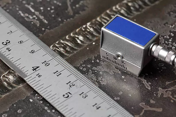
The size and shape of the test piece significantly influence the selection of the transducer. For large, flat surfaces, a larger diameter transducer can be utilized for more efficient scanning. Conversely, smaller transducers are ideal for complex geometries or confined spaces, such as the inspection of small welds or intricate castings. The shape of the transducer, whether flat, curved, or angled, must match the contour of the test piece to ensure effective sound wave propagation and minimal attenuation.
Environmental Factors
Temperature
Temperature plays a vital role in ultrasonic flaw detection. High temperatures can affect both the material properties of the test piece and the performance of the ultrasonic flaw detector. Material properties such as elasticity and density alter with temperature, potentially changing the speed of sound through the material and affecting flaw detection accuracy. Moreover, transducers and coupling media might degrade at extreme temperatures, necessitating the use of temperature-resistant components or specialized high-temperature transducers to maintain inspection effectiveness.
Coupling Media
Coupling media, such as liquids or gels, are used to facilitate the transmission of ultrasonic waves from the transducer into the test material. The choice of coupling medium can impact the efficiency of the ultrasonic flaw detector. Water is a commonly used medium, especially in immersion testing, due to its excellent sound transmission properties. However, for contact testing, gels or pastes are often preferred to minimize mess and ensure good acoustic coupling. In selecting a coupling medium, its acoustic impedance must closely match that of the transducer to ensure optimal sound wave transmission.
Calibration and Maintenance
Calibration Procedures
Calibration is essential to ensure the accuracy and reliability of ultrasonic flaw detectors. Calibration involves setting up the equipment using known reference standards or materials with predefined flaw characteristics. This process involves adjusting several parameters, such as the gain, time base, and ultrasonic velocity, to ensure that the detector can accurately measure and define flaws. Regular calibration checks are necessary to maintain measurement precision, especially before critical inspections.
Routine Maintenance
Routine maintenance of ultrasonic flaw detectors is crucial for prolonging equipment life and maintaining accurate performance. Maintenance procedures include cleaning transducers to prevent buildup of debris, inspecting cables and connectors for wear, and testing battery life to avoid interruptions during inspections. Additionally, software updates should be performed regularly to ensure that the detector benefits from the latest signal processing algorithms and technological advancements.
Advanced Topics
Digital Signal Processing
Advanced Algorithms
Digital signal processing (DSP) techniques significantly enhance the capabilities of ultrasonic flaw detectors. Advanced algorithms such as Fast Fourier Transform (FFT) and wavelet analysis improve the ability to detect and characterize flaws by transforming time-domain signals into their frequency-domain counterparts. This allows for noise reduction, signal enhancement, and the extraction of subtle flaw signals that might otherwise be obscured. Implementing these algorithms helps in accurately identifying and quantifying the flaw define.
Real-Time Analysis
Real-time analysis is a critical feature in modern ultrasonic flaw detection. By integrating microprocessors that can process data instantaneously, these detectors provide immediate results, enabling operators to make quick decisions during inspections. Real-time analysis is particularly beneficial in dynamic environments where fast assessments are required, such as in-line inspection of manufacturing processes or live structural health monitoring.
Automated Ultrasonic Testing
Integration with Robotics
The integration of ultrasonic flaw detectors with robotic systems represents a significant advancement in non-destructive testing. Robots can maneuver transducers with exquisite precision, reaching areas that are difficult or dangerous for human operators. This automation enhances inspection speed, repeatability, and consistency, crucial for large-scale or complex inspections, such as aerospace component testing or nuclear reactor maintenance.
Automated Scanning Systems
Automated scanning systems further improve the efficiency of ultrasonic flaw detection by automating the movement of the transducer over the test material. These systems, equipped with computerized control and positioning, can execute pre-programmed scan patterns to ensure comprehensive coverage and consistent detection accuracy. Automated scanning is particularly advantageous in industrial settings, reducing inspection time and operator fatigue while increasing throughput.
Emerging Technologies
High-Frequency Applications
High-frequency applications are expanding the frontiers of ultrasonic flaw detection. Using frequencies above 20 MHz, these applications can achieve extremely high resolution, essential for detecting micro-level flaws in materials such as advanced composites, ceramics, and thin films. High-frequency ultrasonic testing is invaluable in industries where material integrity at a microscopic level is critical, such as semiconductor manufacturing and biomedical device fabrication.
Novel Transducer Materials
The development of novel transducer materials is driving innovations in ultrasonic flaw detection. Materials such as piezoelectric ceramics and single-crystal compounds provide superior performance characteristics, including improved sensitivity, bandwidth, and durability. These advanced materials enable the creation of more robust and precise transducers, extending the applications of ultrasonic testing to new domains and challenging inspection environments, such as deep-sea exploration or high-temperature engine components.
Integrating these cutting-edge technologies ensures continued improvements in the flaw define process and the overall reliability of ultrasonic flaw detectors. Embracing these advancements not only enhances the detection capabilities but also opens new possibilities for safer and more efficient inspections across various industries.
